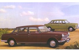
The Austin 3 liter was a substantial car, expanding upon the successful formula of front engined rear wheel drive, whilst incorporating many design features which had made the Mini's, 1100's and 1800's so outstanding.
Lightness was achieved by making the car smaller, while the interior space was increased by using the Issigonis technique of thin doors, a fairly upright seating position and wide wheel track.
The Austin 3 liter's handling was also well sorted, by virtue of the anti-roll properties of the Hydrolastic suspension in conjunction with trailing link independent rear suspension and by putting the wheels at the corners with minimum overhang.
Hydrolastic Suspension Explained
Riding in the back was pretty comfortable too, thanks to the use of low-rate rear suspension in combination with a suspension levelling mechanism. In cars fitted with Hydrolastic suspension the spring rate (deflection in relation to load) had to be the same front and rear because of the degree of see-saw action due to the interconnection of the front and rear units.
In other words, if your weighty mate decided to ride in the back, the Hydrolastic fluid would be pushed out of the rear displacers and into the front ones while the car was still stationary - and this ratio would be maintained until your mate got out.
In laying out the rear suspension the complexity and bulk of the levelling gear made it necessary to separate the actual rubber spring units from the fluid displacers if a level boot floor was to be retained. The springs were therefore located under the rear seats and connected by large bore flexible pipes to the displacers.
The advantage was that, by using this design, the springs could be made double ended, with a rubber doughnut at each end of the canister, thus approximately halving the rate and the progressiveness of each unit. Geometrically the rear suspension was of the trailing link pattern used on the Mini's, 1100's and 1800's. The drive on this first BMC all independent rear wheel drive passenger car was taken to the rear wheels from a final drive mounted on the frame by double jointed shafts incorporating a new type of sliding constant velocity joint.
The rear suspension arms were approximately T-shaped, malleable iron castings with the cross bar of the T pivoting on special rubber bearings. The outer bearing was a bonded pattern slotted to give a high vertical rate and a low horizontal one, with the object of providing rear wheel horizontal compliance and eliminating "thumping". The inner bearings were Metalastik Slipflex units incorating rubber outer sleeves and inner metal to PTFE "antistiction" bearings. Surrounding the inner end of the T, and free to rotate relative to it, was an aluminum suspension housing in which the displacer unit was mounted; a protrusion on the cross bar of the arm acted as a lever and was connected to the Hydrolastic displacer by the usual cone-shaped push rod.
That in turn allowed the whole unit to articulate freely unless the suspension housing was restrained, the height of the rear suspension in turn being decided by the position in which it was held. Then by fitting a hydraulic jack between the chassis and the housing the ride height could be controlled. An Armstrong levelling jack worked in conjunction with two-way valves mounted on the body chassis and connected by rods to the trailing arms. An improvement to the Austin 3 liters Hydrolastic set-up was that the front to rear connection was taken from the displacer below the damper valve, and not from above it, to "build" a degree of pitch into the suspension and to eliminate the characteristic sharp vertical movement.
The front suspension was geometrically of the double wishbone type and was in principle like that first used by Issigonis on the Morris Minor 1000. The upper wishbones were built up from channel section pressings and straddled the front Hydrolastic units. Single transverse links pivoting on ball joints at their inner and outer ends fromed one arm of the bottom wishbones, the other arm was a drag link restrained by a rubber bush at the fixed end to give a calculate degree of horizontal compliance.
In common with the 1800, each suspension unit was based on a separate cast aluminum bracket which served to form an anti-vibration mass and which could be machined precisely to ensure accurate suspension geometry.
Chassis and Body
The 1800 body shell was well suited to the transplantation of a 6 cylinder engine, as it was incredibly strong and could be used as the basis for the body-cum-chassis structure of the new model. New front and rear bays were required to fit the six cylinder engine at one end and the larger luggage boot and final drive unit mounting at the other. That meant that the only panels common to the 1800 were the doors and the roof, although the original stresswork was available when designing the underframe which was formed from double box sills, with the front seat supports and rear seat pan acting as cross-members. The shallow propellor shaft tunnel also impated beam strength.
Up fron, the wings, engine compartment, side panels and grille surround formed a stressed extension of the scuttle. They were spanned by a fabricated box section crossmember to the ends of which the front suspension sub-assemblies were bolted. The steering rack was mounted on the toeboards in the same position as that of the 1800.
A box section transverse member is formed at the back of the rear seat pan and acted as a mounting for the rear suspension arm brackets. Inverted top hat seciton members set fore and aft between the crossmember and teh boot floor acted as abutment for the levelling rams and spread the suspension loads into the structure.
Interior and Instrumentation
The trim of the Austin 3 liter was upgraded, the seat facings using leather and the instrument panel and door cappings using a real walnut veneer. Floor coverings throughout were in a hard-wearing mottled pattern pile carpet. The individual front seats had fully reclining backs, which folded flush with the rear seats to make a bed if required. The rear seat was fitted with a folding armrest. For stowage there were cubby boxes placed under each side of the instrument panel, which incorporated a locking glove box on the passenger side. The mini-style bins on the 1800 doors were retained, and tehre were further stowage lockers on the scuttle panels.
A centre console accomodated a clock, ammeter and oil pressure gauge, along with a generously sized ash tray. A standard sized radio aperture was provided in the console, with the heater controls located below. A ribbon-type trip speedo was placed forward of the driver, and incorporated both fuel and temperature gauges, in turn these being flanked by a series of warning lamps. Following BMC policy with the ADO 16 range a Lucas combined indicator stalk also controlled the headlight high beams.
Heating and ventilation were provided by a Smith's hot matrix air mixing unit mounted under the scuttle and drawing air from an intake in the high pressure area at the base of the screen. Clear Hooters controllable vents were located at each end of the instrument panel provided fresh air.
The Revised C-Type Engine
The trusty C-Type engine was to undergo significant modification. While the bore and stroke and cylinder centres were fixed and cylinder blocks were machined with new equipment, the designers also took the opportunity to save weight despite the requirement that additional metal would be required for three extra main bearing webs. To do this, the designers employed careful pattern work and took advantage of casting techniques that had evolved since the release of the original C-Series engine.
A weight saving of approximately 20lb. was achieved, while also allowing better water passages between the bores. In most other respects however the new engine was similar to the old, with the crankcase extending well below the crankshaft centreline. The main bearing webs were stiffened with radial ribs and the main bearing caps were deeply spigoted into the webs and retained by studs.
Whereas the C series crankshaft ran in four main bearings 1.5in. long and 2.374in. dia., loads in the "29" engine were shared between six bearings 0.90in. long. The extra friction caused by the increase in the main bearing area from 2.62 to 29.0 sq.in. is small and more than compensated for by greater engine smoothness. The new crankshaft was machined from a forging and had nitrided journals and pins; it was balanced by mass balances opposite each crankpin. Torsional vibrations were absorbed by a rubber bonded damper integral with the crankshaft pully.
Connecting rods were split at right angles and were equipped with indium flashed copper-lead bearings while the gudgeon pins were an interference fit in the little ends. For the 3 liter saloon models, hollow-top pistons were used, giving a compression ratio of 8.3:1. Engines destined for the
MGC had flat top pistons giving a compression ratio of 9:1. Four rings per piston, including one Apex oil control ring were used to ensure good gas sealing and oil control without having to resort to the use of too high radial pressures, the amount of springiness in the rings - which had previously been found to cause cylinder bore scuffing.
Once again a Hobourn-Eaton oil pump was driven by a separate skew gear from the crankshaft. The pump position remained unchanged, however due to the fact that the deep portion of the stepped sump was now below the pump instead of at the forward end of the engine, the pump pick up was improved meaning it was unnecessary to increase pump capacity.
Although the six port cylinder head was visually the same as that of the high performance C series, it was a completely new casting, and had a traditional BMC-Westlake kidney-shaped combustion chambers. These had been relocated symmetrical with the cylinder centre-lines instead of being offset to the exhaust side as they were on the C type. Privision was also made for cross drillings to take air from the inlet side of the engine to orifices in the exhaust ports for use when EPAI (exhaust port air injection) was fitted to American market cars.
The valve sizes were the same as fitted to the
Austin-Healey 3000,
1.75 diameter inlets and 1.56 diameter exhausts, the throat diameters being respectively 1.5 inch and 1.31 inch. The Valve material was 21/4 N with Stellite exhaust valve seats to extend valve life to that of the overhaul life of the engine. The fuel mixture was drawn from a pair of 1 3/4 inch SU HS 6 carburetors mounted in a buffer-ended light alloy manifold with an exhaust heated hot spot. Power was claimed to be 118 bhp @ 4750 rpm, with 152 lb. ft. of torque @ 2500 rpm. A multi-groove crankshaft pulley provided drives for the many ancillary services. On home market cars there were the alternator, water pump and fan on one triangulated drive and an extra pulley for the levelling pump. The hydraullic pump for power steering used a third pully, while there was an additional belt installed on US bound cars to operate the EPAI air pump.
Transmission
You could option the Austin 3 liter with either the BMC four speed all-synchro manual gearbox of the Borg-Warner automatic transmission, with final drives of 3.91 and 3.56 to 1 respectively. Both transmissions had the gear shift lever mounted on the transmission tunnel, the automatic transmission having D1 and D2 as well as low gear "lock-up" positions. The drive was by a one-piece propellor shaft with Hooke joints to the BMC hypoid final drive unit. To insulate the body from transmission noise the back of the final drive was mounted on a subframe which in turn was attached to the body on rubber mountings at two widely separated points.
The final drive nose-piece was extended well forward and had a third mounting point at its extremity. By separating the attachment points to the hull in this way it was possible to control torque reaction and at the same time use soft rubbers of the right consistency to absorb transmission noise. Solid drive shafts embodying a new type of Hardy Speicer constant velocity plunging and self-aligning joint took the drive out to the rear wheels.
Steering
Rack-and-pinion powere steering was fitted to the Austin 3 liter, requiring 3.94 turns lock to lock. Manufactured by Cam Gears Ltd., it was similar in design to that fitted to the Wolseley 18/85, although steering torque was sensed by mounting the pinion on a swinging arm, which actuated the power valve, in place of the sliding pinion block used in the Wolseley. Hydraulic pressure was provided by an engine driven Hobourn-Eaton hydraulic pump.
Brakes
Although early versions had only a single circuit disc and drum layout, the fitting of a direct action "pedal pusher" servo indicated that a dual circuit system would soon follow. The use of new Girling 3-spot brake calipers meant there was a larger rubbed area for a given pad area when compared to 2-spot. Having one pad on the inboard side of the caliper and two pads, of a total area the same as that of the single pad, located radially on the outboard leg of the caliper. The centre of the single pad was in line with the land between the two outboard pads. With the 10.4 inch diameter front discs fitted the rubbed area was 224 sq. in. The rear brakes were 9 x 2 1/4 in. drums.
With the Austin 3 liter, BMC managed to produce a car with advanced specifications for the time, without losing the "old-fashioned" advantages of knee room, comfort and spaciosness. And while interior room made the car spacious, it was 2 inches shorter and three inches lower that the car it replaced.